In this article, we'll explore the steps of ER modelling for database design. By the end, you will know what database design is and how to create an entity-relationship diagram (ER). In addition, you will also learn how to translate an ER from a case study.
In addition, you may want to check some related posts like Picking The Right SQL Database Flavor For You. Or, maybe you want to learn about CRUD Operations: Understanding The Role in MySQL.
What is Database Design?
Database design is one of the most important skills you can own today. However, you might be lost on what it actually means.
In simple terms, it is to draw up a structure for a database dev to implement a business's system.
What is an ER Design?
An Entity Relationship (ER) design is a top-down visual schematic of the database. In other words, it is a flowchart of entities-- group of objects with similar properties-- attributes and their relationships.
An ER diagram, or ERD, is part of conceptual database design. Conceptual design is free of RDBMS selection or physical constrains. This facilitates the logical and physical database design.
ERs visually explain the relationship types between entities and their constraints, using a modelling language.
UML, or Unified Modelling Language, describes ER diagrams. For instance, only a particular set of symbols represents ER diagrams.
Why Use ER Diagrams?
After that, if you're wondering why you should use ER diagrams altogether, then let's see some reasons below:
- Provides a preview of how your tables connect, their keys and the attributes
- Helps to visualize entities, attributes, relationships together
- Serves as blueprint for conversion into relational tables
Get Started With ER Modelling?
Entity
An entity is an object or class, sharing similar properties. There are two types of entities: strong and weak entities.
- Strong entities: has its own primary key and exists independently.
- Weak entities: depends on a strong entity for existence.
Rectangles represent entities in UML.
Relationship
Relationship type defines the connectivity of entities with each other in an organized manner. This allows the database dev to see how entities interact. Sometimes, there are relationship type attributes as well.
There are four types of relationships:
- 1-to-1
- 1-To-Many
- Many-To-1
- Many-To-Many
A line typically represents a relationship in UML, labelled with a name and its multiplicity constraint.
Attribute
Attributes are the properties that define an entity. There are various types of attributes:
- Single-valued: Attributes that return one instance for a tuple. For instance, first name.
- Multivalued: Attributes that may return multiple instances for a tuple. For instance, telephone number-- you may have multiple numbers.
- Derived: Attributes that are dependent for their values. For instance, age is derived from the birthdate.
- Simple: Non-divisible (atomic) attributes. For instance, ssn id.
- Composite: Divisible attributes sometimes grouped together. For instance, address may be subdivided into street, city, state, country, and zip code.
Attributes are listed in the second compartment of the entity in UML.
An Example to Help Illustrate ER Design: From Zero to Database Designer
Case Study: A Video Rental Company
The case study describes the data requirements for a video rental company.
The video rental company has several branches throughout the USA. The data on each branch is the branch address made up of street, city, state, and zip code, and the telephone number. Each branch has a branch number, which is unique throughout the company. Each branch is allocated staff, which includes a Manager.
The Manager is responsible for the day-to-day running of a given branch. The data held on a member of staff is his or her name, position, and salary. Each member of staff has a staff number, which is unique throughout the company.
Each branch has a stock of videos. The data held on a video is the catalog number, video number, title, category, daily rental, cost, status, and the names of the main actors and the director. In addition, the catalog number uniquely identifies each video. However, in most cases, there are several copies of each video at a branch, and the individual copies are identified using the video number.
Video Rental Company (Continued)
Each video has a category such as Action, Adult, Children, Drama, Horror, or Sci-Fi. The status indicates whether a specific copy of a video is available for rent. Before hiring a video from the company, a customer must first register as a member of a local branch.
The data held on a member is the first and last name, address, and the date that the member registered at a branch. Each member has a member number, which is unique throughout all branches of the company. Once registered, a member is free to rent videos, up to a maximum of ten at any one time.
The data held on each video rented is the rental number, the full name and number of the member, the video number, title, and daily rental, and the dates the video is rented out and returned. Therefore, the rental number is unique throughout the company.
Designing Steps (Basic):
Scared by the length of that case study? Worry not.
The easiest way to understand and translate any case studies is to break it down. Therefore, this is what we will do below, explaining the steps you must take.
Firstly, identify the main entities from this case study for your database schema. You can do this by circling the key Nouns you find.
What are the possible entities? For instance, the first one is the Branch.
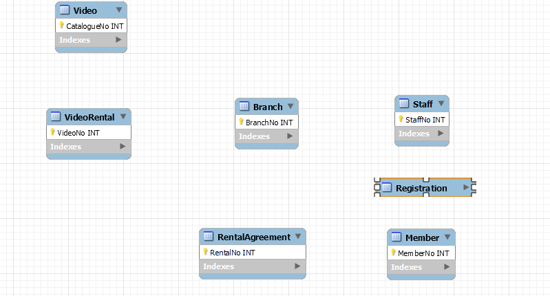
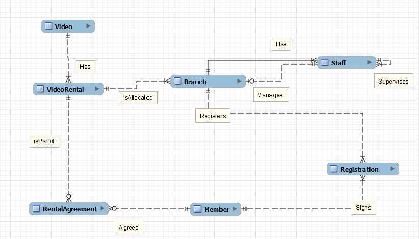
Then, you come across Staff, Member/Customer, Video. VideoRental, and Rental Agreement. After that, there's one more entity that could be considered a weak entity here-- Registration. Perhaps, you could also try an alternative. That is, to use Registration as an attribute of the relationship between branch and member.

After that, identify the relationship types between these entities. You can do this by establishing how one entity links to another. For example a staff member supervises the rest of the staff. Hence, this is a recursive relationship--"supervises" for the supervisor(part of staff entity) and "supervised by" for the remaining staff. Moreover, a member must "agree" to Rental Agreement. Try to determine as many links as you can.
Designing Steps (Advanced):
For example, ".. branch number is unique throughout the company" states that branch number is branch's primary key.
The third step is to determine the primary and secondary keys in the entities. A primary key (PK) is the distinguishing attribute of an entity. You can identify them by reading the case study carefully-- you may also need business logic.
Secondary keys are candidate keys that could not independently distinguish the tuples. Consequently, they were not chosen as PKs and they are also called Alternate keys.
After this, a crucial step is determining multiplicity constraints. This is a sum of cardinality and participation constraint. In simple words, multiplicity constraint identifies the involvement of an entity in a relationship.. It is read as "at least.. to as many as".
Participation represents if occurrence of an entity in a relationship is mandatory or not. It may be 0 or 1. On the other hand, cardinality represents the maximum number of occurrences of that entity. It may be 0,1... or n.
But, how do you do this? Easier said than done, right?
You must have some business logic and know-how of an individual business to do well here. For instance, let's suppose the relationship between branch and staff. The way to identify multiplicity constraints is to visualize the problem.
Is staff mandatory for a branch to exist? Is branch mandatory for staff to exist?
These questions result in participation (P).
For each branch, how many staff can exist? For a managerial staff, how many branches may exist?
These questions result in cardinality (C).
Multiplicity is written as "P..C".

Conclusion
In conclusion, I hope you were able to learn how to convert a real-life case into an ERD. The case study may have looked scary initially, but after breaking it down, it was quite simple to deal with, wasn't it? Therefore, the key-- always-- is to follow a step-by-step procedure for such cases.
Please like the post if you learned something new here or appreciated the efforts. Subscribe to our blog to stay updated on new content. Lastly, let us know your thoughts about this post in the comments. Moreover, let us know if you face any issues.
Thanks for reading. Stay safe and stay healthy.
