Categories
AI & Emerging Technology Software Development

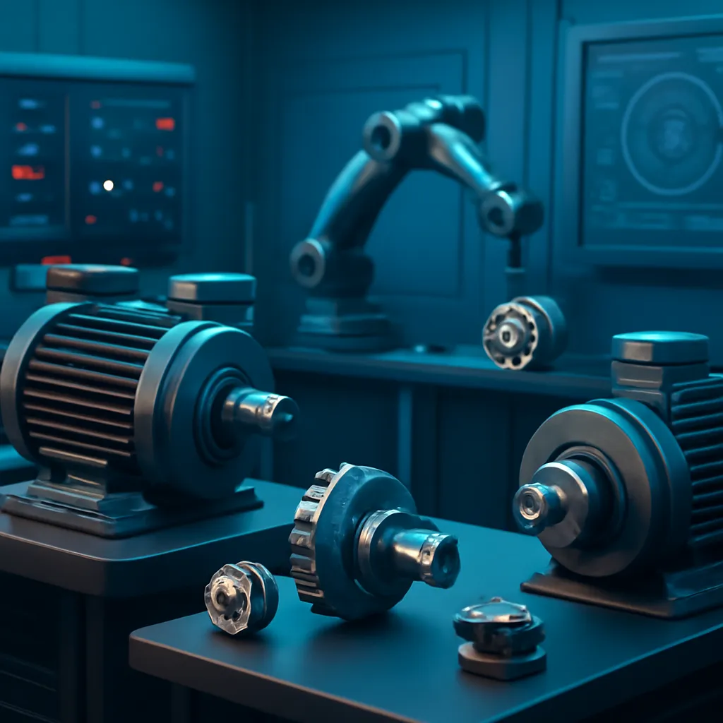
Electric Motor Scaling Laws and Their Impact on Robot Actuator Design

Why Electric Motor Scaling Laws Matter

Electric motors are the backbone of robotic actuation—whether driving industrial arms, legged robots, or precision medical devices. Yet, as requirements change and robots scale up or down in size, the relationships between motor size, torque, speed, and inertia do not scale linearly. Ignoring these scaling laws leads to wasted energy, sluggish response, or even instability and mechanical failure.

For robotics engineers and system architects, understanding these physical constraints is not just an academic exercise. It’s a prerequisite for specifying actuators that balance speed, strength, energy efficiency, and control fidelity. As robots enter more domains—from warehouse logistics to surgical automation—these trade-offs are moving from “nice to know” to “mission critical.”

Scaling Laws in Electric Motor Design

Scaling laws describe how key motor properties change as you alter the size or design of the motor. The most relevant parameters for robotics are:

  • Torque (τ): The rotational force the motor can exert.
  • Power (P): The rate at which the motor can do work.
  • Rotor Inertia (Jm): The resistance of the motor’s rotor to angular acceleration.
  • Reflected Load Inertia (Jref): The effect of the load’s inertia as seen “through” the transmission (gearing).

Let’s break down the relationships based on established engineering literature and recent research (Robot Daycare, Vrije Universiteit Brussel).

How Torque, Power, and Inertia Scale

  • Torque (τ): For a given motor technology, torque scales roughly with the square of the characteristic dimension (e.g., rotor radius R):
    τ ∝ R²
  • Power (P): Power output is proportional to volume, so:
    P ∝ R³
  • Rotor inertia (Jm): Inertia scales with mass and the square of the radius, so:
    Jm ∝ R⁵

This means that doubling a motor’s size increases torque 4x, power 8x, but inertia 32x. Inertia grows much faster than usable output!

Transmission and Reflected Inertia

Motors are rarely connected directly to robot joints; gearboxes or other transmissions are used to increase torque or change speed. The reflected inertia seen by the motor is:

J_ref = J_load / N²

Where J_load is the load inertia and N is the gear ratio. Higher gear ratios reduce reflected load inertia, making the system “feel lighter” to the motor—but at the cost of speed and backdrivability.

However, as recent actuator research notes, if you hold motor mass and continuous torque constant and adjust the gap radius and gear ratio together, output torque and total reflected inertia can remain independent of the gear ratio. This is non-intuitive and crucial for advanced actuator design.

Inertia in Robot Actuators: Implications and Mitigation

Inertia—both of the motor and the load—has a profound impact on how a robot moves, how precise it can be, and how “interactive” or safe it is around humans.

Control and Responsiveness

  • Bandwidth: High rotor inertia limits acceleration; control loops must be slower to avoid instability.
  • Backdrivability: Robots with high reflected inertia resist external forces, making them feel “stiff” and less safe for collaboration or rehabilitation.
  • Energy Efficiency: More inertia means more energy spent starting/stopping movement, which can dominate energy use in repetitive or dynamic tasks.

Failure Modes and Limitations

  • Overshoot and Oscillation: High inertia can cause overshoot or oscillatory behavior, especially in lightly damped systems.
  • Reduced Agility: Large, heavy actuators cannot change direction or speed rapidly—critical for legged robots and drones.
  • Wear and Tear: Larger inertias place greater stress on gears, bearings, and structural elements.

Design Trade-Offs

  • High gear ratios reduce required motor torque but increase output reflected inertia—degrading compliance and backdrivability.
  • Direct-drive (no gearbox) minimizes reflected inertia but requires much larger, heavier motors for the same output torque, increasing system mass and cost.
  • Advanced gear designs (e.g., harmonic drives) can offer high ratios with low added mass but may introduce friction and compliance issues.

Mitigation Strategies

  • Material Choices: Lightweight rotors (aluminum, carbon fiber) reduce inertia.
  • Optimal Gear Ratios: Balance torque amplification with manageable reflected inertia.
  • Intelligent Control: Model-based control (e.g., computed torque, feedforward) compensates for inertia dynamically.
  • Series Elastic Actuators: Introduce compliance to absorb shocks and improve safety.

For a deep dive, see the open-access paper Scaling laws for robotic transmissions.

Practical Examples: Code and Real-World Performance

To ground these concepts, let’s examine a code example using Python and PyBullet (a mainstream robotics simulation framework). This snippet compares joint responsiveness for actuators with different rotor inertias.

The following code is an illustrative example and has not been verified against official documentation. Please refer to the official docs for production-ready code.

import pybullet as p
import pybullet_data
import numpy as np

# Connect to physics server
p.connect(p.GUI)
p.setAdditionalSearchPath(pybullet_data.getDataPath())
robot_id = p.loadURDF("kuka_iiwa/model.urdf", useFixedBase=True)

# Example: Set joint inertia for joint 2
joint_index = 2
for inertia in [0.001, 0.01, 0.05]:  # kg*m^2
    p.changeDynamics(robot_id, joint_index, jointDamping=0.01, localInertiaDiagonal=[inertia, 0, 0])
    p.resetJointState(robot_id, joint_index, 0)
    p.setJointMotorControl2(robot_id, joint_index, controlMode=p.POSITION_CONTROL, targetPosition=1.0)
    p.stepSimulation()
    # Record position response (code for plotting omitted for brevity)

In practice, you’ll observe that as inertia increases, the joint takes longer to reach the target position and may overshoot or oscillate unless control gains are tuned down.

For real robot hardware, the same principles apply—modern arms (e.g., Universal Robots UR series, Franka Emika) carefully balance gear ratios, motor size, and rotor inertia to maximize both safety and precision.

Comparing Motor Sizes, Inertia, and Performance

The following table summarizes how motor size, torque, power, and inertia scale (assuming similar designs and materials):

ParameterScaling LawExample: 2x Size IncreaseImplication
Torque (τ)∝ R²4xHigher load capacity
Power (P)∝ R³8xFaster/heavier tasks possible
Rotor Inertia (Jm)∝ R⁵32xMuch slower response
Reflected Load Inertia (Jref)∝ 1/N²1/4x (for 2x gear ratio)Improved control, but less backdrivability

The challenge: increasing torque and power is straightforward by making motors bigger, but rapidly growing inertia limits how quickly and safely robots can move.

What to Watch Next in Robot Actuator Design

The robotics community is actively seeking solutions to the inertia scaling bottleneck:

  • Novel Materials: Carbon fiber and advanced composites are being used for rotors to reduce inertia without sacrificing strength.
  • Variable Transmission Systems: Adaptive gearboxes can change ratios on the fly, optimizing torque and speed throughout a task (source).
  • Backdrivable and Series Elastic Actuators: These approaches improve safety and compliance for human-robot interaction by reducing effective output inertia.
  • AI-Driven Control: Reinforcement learning and model predictive control algorithms can dynamically compensate for inertia and nonlinearities, improving precision and energy efficiency.

As field deployments of collaborative robots and autonomous systems accelerate, actuator designs that intelligently balance scaling laws and inertia will define the next generation of robotics.

Key Takeaways:

  • Electric motor scaling laws mean that as motors get larger, torque and power increase rapidly—but rotor inertia grows even faster, limiting responsiveness and control.
  • Gearboxes can reduce required motor torque and reflected load inertia, but increase output inertia and reduce backdrivability.
  • Modern robot actuator design requires careful trade-offs among torque, inertia, energy efficiency, and safety, often leveraging advanced materials and control algorithms.
  • Research-backed design—grounded in physics and validated by simulation—remains essential for deploying reliable, high-performance robots at scale.

For more technical detail and foundational research, see:

Bookmark this guide as a technical reference for actuator scaling and inertia implications. For implementation advice or simulation best practices, return as new research and industry benchmarks emerge.

Sources and References

This article was researched using a combination of primary and supplementary sources:

Supplementary References

These sources provide additional context, definitions, and background information to help clarify concepts mentioned in the primary source.