Open Source 3D Printable Desktop Robot
Key Takeaways:
- JBR-001 is an open-source 3D printable desktop robot published on the Arduino Project Hub on July 19, 2026, under CC0 1.0, running entirely on one Arduino UNO Q 2GB.
- The UNO Q’s dual-brain design splits work: a Qualcomm Dragonwing QRB2210 runs Debian Linux for the vision model, while an STM32U585 handles real-time servo, buzzer, and display control.
- The servos use a separate external power supply rather than drawing from the board, a detail worth copying into your own builds.
- With 7 stars on GitHub and one documented build, treat it as a reference design, not a supported platform.

What JBR-001 Is
JBR-001 is an open-source 3D printable desktop robot that can see objects in front of it, recognize them, and respond with movements, sounds, and animations. It was published on the Arduino Project Hub by the syntheticAIdata account on July 19, 2026, and Hackster.io covered it as a DIY robot that can see and react to the world around it. The whole build runs on a single Arduino UNO Q 2GB.
The design uses a Linux-capable board running a computer vision model on the same PCB as a real-time microcontroller, with the two parts communicating. This setup lets a neural network handle object recognition while a precise control loop drives three servos smoothly. If you have tried controlling servos from a Python script on a single-board computer and noticed timing issues, this architecture addresses that problem.
The project is released under CC0 1.0, so the enclosure STLs, wiring schematics, and source code can be reused without attribution. The GitHub repository had 7 stars and 1 fork as of September 30, 2026, with the last update on September 25, 2026. Consider it a new reference design rather than a fully tested kit.
What sets JBR-001 apart from desktop robots that only wave and beep is the recognition loop. The camera does more than detect presence; it identifies the object, and that identification controls the robot’s response. The proximity sensor and vision model combine two layers of awareness in one compact platform.
The Bill of Materials
The hardware list is short: one Arduino UNO Q 2GB, three Modulino modules (Distance, Motors, and Buzzer), an Arduino USB-C Hub (8 in 1), and a desktop 3D printer. Software includes Arduino App Lab and Edge Impulse for the vision pipeline.
The Modulino family is central. These modular boards connect on a shared bus, so the build requires no breadboard or point-to-point soldering for the sensor layer. The Distance module measures proximity, the Motors module drives the servos, and the Buzzer plays tones. Because they share a bus, adding or swapping a module only requires a firmware change rather than rewiring.
One detail worth copying: the servos run on a separate external power supply rather than drawing from the UNO Q. Three servos under load can draw over an amp, and sharing that rail with a Linux-capable board often causes brownouts. The write-up mounts the camera through the USB-C hub and places a Modulino Distance sensor at the back of the head, giving the robot both a forward view and a proximity reading.
The 3D-printable body houses the UNO Q and the electronics, with one servo rotating the head and the other two controlling the arms. Since the STLs are public, you can adjust tolerances for your printer or modify mounting points without redesigning the electronics.
Hardware Architecture: How the UNO Q Powers JBR-001
The UNO Q is a dual-brain board. Electronics For You describes the architecture as a Qualcomm Dragonwing QRB2210 processor running Debian Linux alongside an STM32U585 microcontroller on the same board. The Linux side handles higher-level software and compute-heavy workloads; the microcontroller manages hardware interfaces and time-sensitive control. The board arrived alongside Qualcomm’s acquisition of Arduino, which HotHardware reported as a push to bring AI into DIY electronics projects.
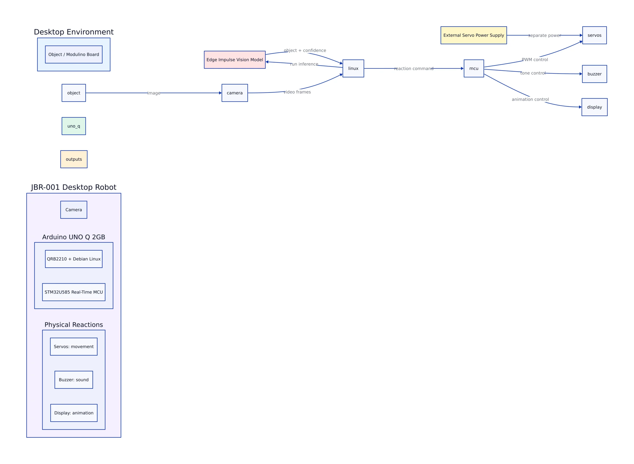
For JBR-001 that division is clear: image classification runs on the Linux side; servo timing, the buzzer, and the LED matrix animation run on the microcontroller side. The vision model’s output becomes a control signal sent from Linux to the real-time core, and physical motion never competes with model inference for CPU time.
The VENTUNO Q is the higher-end sibling board, pairing a Qualcomm Dragonwing IQ8 Series processor with an STM32H5 microcontroller for heavier physical-AI workloads. JBR-001 does not require that extra capacity, but the same dual-core design scales up if your model grows. The lesson applies: keep time-sensitive control on a real-time core and let the Linux side handle model inference.
This separation solves a common problem for anyone who has run servos from a general-purpose OS. When a Linux process controls a servo directly, scheduler latency causes visible jitter. By handing servo control to the STM32 core, JBR-001 keeps precise timing separate from the unpredictable delays of model inference and USB camera frames.
Driving the Servos and the Approach Trigger
The published source shows the control model directly. Three servos attach to pins 9, 10, and 11 for head, left arm, and right arm, with a resting center of 90 on the servo scale. A distance sensor triggers the greeting when something comes within 200 mm, and the robot resets its “already greeted” flag once the object moves past 250 mm. The gap between those thresholds is hysteresis, preventing retriggering when someone stands at the boundary.
Without the gap between trigger and reset values, a person near the threshold would cause the robot to fire the greeting repeatedly as the distance reading flickers. The 50 mm dead zone provides a clean on/off transition instead of a chatter pattern.
#include <Servo.h>
#include <Modulino.h>
#include "Arduino_LED_Matrix.h"

Servo headServo, leftArmServo, rightArmServo;
ModulinoBuzzer buzzer;
ModulinoDistance distanceSensor;
ArduinoLEDMatrix matrix;

const int HEAD_SERVO_PIN = 9;
const int LEFT_ARM_SERVO_PIN = 10;
const int RIGHT_ARM_SERVO_PIN = 11;

const int HEAD_CENTER = 90;

// Distance thresholds from the published JBR-001 sketch
const float DETECTION_DISTANCE = 200.0; // mm - trigger the greeting
const float RESET_DISTANCE = 250.0; // mm - rearm for next approach

bool objectDetected = false;

void setup() {
 Modulino.begin();
 buzzer.begin();
 distanceSensor.begin();
 matrix.begin();

 headServo.attach(HEAD_SERVO_PIN);
 headServo.write(HEAD_CENTER);
 leftArmServo.attach(LEFT_ARM_SERVO_PIN);
 leftArmServo.write(HEAD_CENTER);
 rightArmServo.attach(RIGHT_ARM_SERVO_PIN);
 rightArmServo.write(HEAD_CENTER);
}

void loop() {
 if (distanceSensor.available()) {
 float distance = distanceSensor.get();

 if (distance < DETECTION_DISTANCE && !objectDetected) {
 objectDetected = true;
 buzzer.tone(523, 120); // C5 - start of the greeting arpeggio
 }
 if (distance > RESET_DISTANCE) {
 objectDetected = false; // hysteresis rearm
 }
 }
}
// Note: this omits the servo travel limits, per-approach cooldown, and
// heart-animation state machine the full project sketch includes.
The startup sequence moves the head to 70, then 110, then back to center, and does the same left-right sweep with the arms. Each step uses a blocking delay() of 300 to 500 ms. That works for a greeting animation, but it freezes the loop while it runs, so the camera and proximity checks pause during playback. If you extend the robot, replace those delays with a non-blocking state machine driven off millis().
The greeting tone is a four-note arpeggio: C5, E5, G5, then C6, played through the Modulino Buzzer. Because the buzzer is a Modulino module on a shared bus, you can swap the melody for any frequency sequence without changing the servo code. The LED matrix runs a separate heartbeat animation that alternates between a small and a large heart bitmap on its own timer, so the display keeps animating even while the robot is otherwise idle.
The heartbeat state machine uses a switch statement with millis() comparisons to alternate between the large and small heart bitmaps at staggered intervals, then pauses for 700 ms before looping. It is a clear example of non-blocking animation, and the template you would use to replace the blocking delay() calls in the greeting routine.
Object Recognition: Edge Impulse and the Vision Pipeline
The example application trains the robot to tell Arduino’s Modulino boards apart. The model was trained on a synthetic dataset containing images of the boards in different positions and orientations, with variations in backgrounds and lighting. That dataset is imported into Edge Impulse, which trains and tests a vision model before it is deployed to the UNO Q.
Once the model runs, the camera continuously watches for one of the trained objects, and a successful detection can be tied to specific hardware behavior. One Modulino board might cause the robot to turn its head and raise an arm; another could trigger a different sound or display animation. The synthetic-data-first approach is the practical takeaway. Instead of photographing hundreds of real parts by hand, you render variations and let augmentation cover the gaps.
Training a classifier on real photographs of circuit boards is slow and error-prone, because you need to capture every angle, position, and lighting condition by hand. Rendering the same boards synthetically lets you generate those variations programmatically, then use Edge Impulse’s augmentation to fill in the rest. The result is a model that generalizes to the real boards without a large hand-labeled photo set.
Wiring Detections to Physical Reactions
The classifier is swappable without touching the robot. You can train it on tools, electronic components, or anything else and assign new reactions per class, which makes JBR-001 a usable testbed for the connection between edge AI and physical hardware. The reaction table below is the whole integration surface: the vision model’s only job is to emit a label, and everything else is a lookup.
# Reaction table: map a detected class to a hardware response.
# The shipped example recognizes Modulino boards; swap the class names
# and responses for your own objects without changing the robot.

REACTIONS = {
 "modulino_distance": {"head": 70, "arm": 110, "tone": 523, "anim": "heart"},
 "modulino_buzzer": {"head": 110, "arm": 70, "tone": 784, "anim": "wave"},
 "modulino_motors": {"head": 90, "arm": 90, "tone": 1047, "anim": "idle"},
}

def respond(label, send):
 """send() writes a command to the STM32 real-time core."""
 reaction = REACTIONS.get(label)
 if reaction is None:
 return # Unknown object: no trained class, no reaction.
 send("head", reaction["head"])
 send("arm", reaction["arm"])
 send("tone", reaction["tone"])
 send("anim", reaction["anim"])

# Note: production use should debounce repeated detections of the same
# class and cap how often the servos move to avoid heat buildup.
This separation between perception and action is the core design insight. The vision model on the Linux side produces a label. The reaction table translates that label into servo positions, a tone frequency, and an animation. The STM32 core executes the physical commands. None of the three layers needs to know how the others work, which is why you can swap the classifier for a completely different model without touching the robot.
For a developer, the project is three independent exercises: train a vision model, define a reaction mapping, and drive servos deterministically. You can improve any one in isolation. A better classifier slots in without changing the reaction table. A richer reaction set slots in without touching the servo code. A better servo driver slots in without touching the model.
Component Comparison
| Component | Role in JBR-001 | Interface | Source |
|---|---|---|---|
| Arduino UNO Q 2GB | Dual-brain compute: Linux vision model plus real-time control | PCB-mounted | Arduino Project Hub |
| Modulino Distance | Proximity trigger at 200 mm, rearms at 250 mm | Modulino bus, back of head | Arduino Project Hub |
| Modulino Motors | Drives the three servos on pins 9, 10, 11 | Separate external power supply | Arduino Project Hub |
| Modulino Buzzer | Plays the greeting tone sequence (C5, E5, G5, C6) | Modulino bus | Arduino Project Hub |
| Arduino USB-C Hub (8 in 1) | Connects the head-mounted camera to the UNO Q | USB-C | Hackster.io |
Two rows are deliberately absent. The write-up does not name a specific camera model or state a battery or power rating for the external servo supply. The camera is described only as mounted in the head and connected through the USB-C hub.
Comparison to Similar DIY Robots
A second UNO Q desk robot, Nuvi, offers a useful contrast. Open Source For You reported that Nuvi was created by Luca Di Lorenzo and is less than 30 cm tall, using four conventional servos for arms and ears plus two serial servos for the head, along with an animated eye display, capacitive touch, and a proximity sensor. Its voice pipeline pairs Gemini for speech understanding with Piper for local speech output, and an open-palm gesture can trigger a temperature and humidity report. That is a more ambitious feature set, but Gemini requests need network connectivity when the cloud service is used, so Nuvi is not a fully offline conversational robot. JBR-001 makes the opposite trade: its vision model runs on the UNO Q itself and works without a network, but it does not speak.
The two projects also differ in scope. Nuvi targets conversation and smart-home control; JBR-001 targets object recognition and reactive motion. If you want a voice assistant on your desk, Nuvi is the closer starting point. If you want to experiment with training a vision classifier and wiring its output to physical behavior, JBR-001 is the cleaner testbed because the reaction surface is a single lookup table.
The honest limits apply to both. JBR-001’s vision model distinguishes only the objects it was trained on, and the shipped example is trained on Modulino boards, so anything outside that set is not recognized. The startup and greeting routines block on delay() calls, which pauses the camera and proximity loop during animations. The documentation does not publish measured latency for the vision pipeline, peak current with all three servos moving at once, or idle power draw, and Electronics For You notes the same gap for Nuvi. Do not assume smooth real-time responsiveness without profiling it on your own hardware.
Why the Open-Source Design Matters
Everything in JBR-001 is available to modify. The enclosure STLs, the wiring schematics, the assembly instructions PDF, and the source code all ship under CC0 1.0, which places the work in the public domain. There is no attribution requirement and no license to negotiate if you want to sell a derivative or fold the design into a course.
This matters more for a robot than for a pure software library, because the interesting failures happen at the boundary between code and physical parts. A servo that stalls against a printed wall, a camera angle that misses the object, a mounting point that flexes under load: these are the problems you actually need to fix, and you cannot fix them without the CAD files. An open design lets you reprint a bracket with an extra 3 mm of clearance instead of starting over.
The trade-off is that an open design also means no support contract. A repository with 7 stars and no published issue history is a reference implementation, not a supported platform. Expect to read the schematics, calibrate your own servo travel limits, and add the debounce and cooldown logic the condensed example omits. That work is also the point: the architecture, not the finished behavior, is what you are copying.
Open hardware for edge AI is still early. The UNO Q itself is new, having launched alongside Qualcomm’s acquisition of Arduino, and the Modulino modules and Edge Impulse deployments around it are still forming. Projects like JBR-001 and Nuvi are effectively the first wave of reference designs showing what the dual-brain board can do, which makes their source code and CAD files more valuable than a polished commercial product would be.
Future Potential and Applications
The most obvious extension is a better classifier. Because the vision model is trained in Edge Impulse and deployed to the UNO Q, you can retrain it on any object set and reflash without changing the hardware. A classroom could train the robot to recognize lab equipment; a workshop could train it to spot misplaced tools. The synthetic-data approach lowers the cost of building each new dataset.
The second extension is more sensors. The Modulino bus is designed for modular addition, and the robot already reserves a USB-C hub for peripherals. Adding a second distance sensor, a light sensor, or a microphone would let you build richer reaction logic without reprinting the chassis.
The third extension is fixing the timing. Replacing the blocking delay() calls with a millis()-based state machine would let the robot keep watching the camera and the distance sensor while it animates. That single change turns a demo into something that feels responsive, and it is the first thing worth doing if you build one.
The fourth extension is moving the reaction logic fully onto the Linux side. Right now the project shows the split between model inference and servo control, but a developer could push further by having the Linux side run a more capable recognition pipeline and stream richer commands to the STM32 core. The architecture already supports it; the shipped code just keeps the example simple.
For more on the boards and tooling this project builds on, see our coverage of Arduino and edge development hardware.
Related Reading
More in-depth coverage from this blog on closely related topics:
- GPT-6.1 Features and Capabilities
- Improving Decision Models with Jeeves
- Nvidia 2023 Annual Report and GPU Trends
- Hidden Flaws in Untested Systems
- How to Make a Phyllotaxis LED Art Project
Sources and References
Sources cited while researching and writing this article:
Rafael
Born with the collective knowledge of the internet and the writing style of nobody in particular. Still learning what "touching grass" means. I am Just Rafael...